An idea to make copying easier
= A7&B7


I can’t find the “Z” axis for pop2 rotation anywhere in the excel file ![]()
i order FYSETC E4 board with built-in Wi-Fi and Bluetooth 4 pcs TMC2209 240MH - FYSETC OFFICIAL WEBSITE
integrated web browser for upload gcode (all-in-one)
1 Like
Hello, when I made the excel file, I hadn’t made the Z axis yet.
I am to redo a complete tutorial with the links of the parts, files, etc… to put it in a single post and make it clearer.
2 Likes
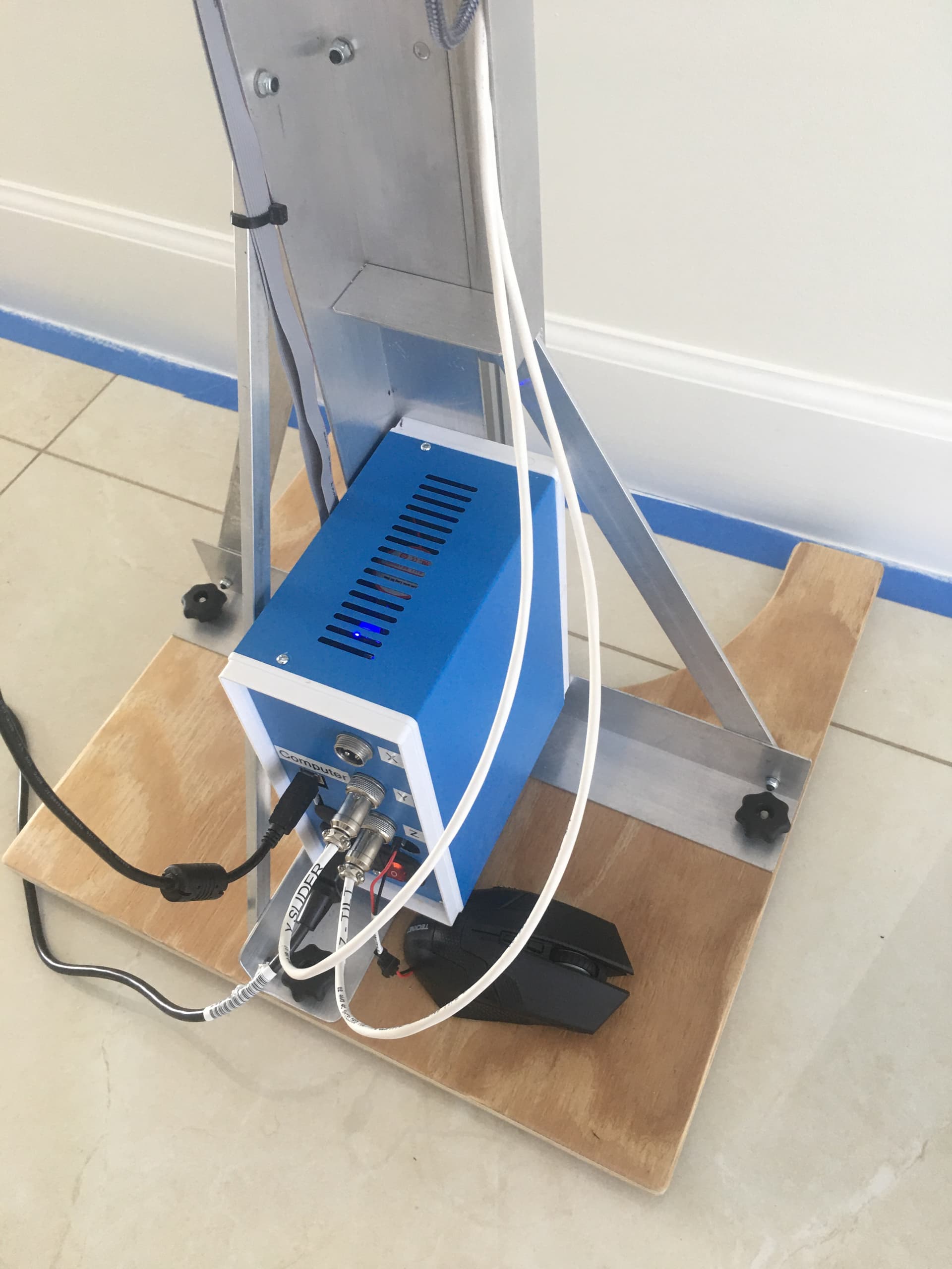
Status of my “MoussArena Slider”
I changed to a “MKS-DLC32” GRBL control board, which has a 3.5" touch screen.
Had to upgrade the original Laser firmware for the CNC firmware.
The display provide XYZ location and allows you to select gcode files.
The MKS-DLC32 has wifi so once the board is on the local network, it is easy to access and load gcode.
The board runs GRBL, but only Windows applications that can communicate with ESP32 work. I found bCNC and ugsplatform to work fine by USB
The Z stepper I replaced with a gear headed nema 17 P/N 17HS13-0404S-PG5, in order to gain some additional resolution of the Z axis.
The spindle connections on the control board operate a 24v relay, which provides the NO / NC contact to an external wireless mouse. When I run the gcode;
M3 S10000
G4 P0.5
M5 S0
G4 P5
M3 S10000
G4 P0.5
M5 S0
The wireless mouse sends the signal which is programmed to the “Space” bar to operate Revoscan program for a 5 second scan.
I built a 3 dimensional scanning fixture (Still a phototype), to take advantage of the “Sliders” ability to control the scanning environment. I can start a scan looking up from the bottom of the part at a -29 degree angle and then transitioning to looking down on the part at a +25 degree angle, with the part remaining centered in the scan window the whole time and without the scanner losing track
SUPER COOL
The gcode to make a transition with the part centered in the scan window, is just including both the Y and Z axis commands in one line. IE
G01 Y230 Z-29 F1000
G01 Y570 Z25 F1000
Added a wood top to the X axis turntable, which greatly improved the feel of standing on the turntable.
Added two M5 nylon screws with embeded nuts, on each side of the sider plates to provide a touch of friction, so the slider does not drop when off.


5 Likes
Brilliant ![]() could you make a small video of the use?
could you make a small video of the use?
1 Like
@Miamijerry WOW … ![]()
How many amps is the motor in the roto table (to set the vref on the driver)?
Some ideas for gcode generator
1 Like
Not sure of the motor specs, but I set each of my axis to .360 amps measured with an ampmeter
1 Like
As requested
1 Like
Great demonstration of the slider, I love the DIY.
we can still bring a lot of little things that simplify the work like, a Gcode generator, pause and activate the scan from the slider, and a lot of little things that I think of!
today I made myself the 6mm plexiglass plates on the CNC, because I don’t print ABS…
but you have made good progress in the ideas Congratulations to you and thank you
business to follow…
better version with macros
Experimenting with different methods of using the slider for a whole body scan.
Added a 5" spacer/base to provide the height needed to scan the top of my head, this helped a lot.
Trying vertical scans top to bottom with the camera tilted down, fuse the first scan and tried a second scan with the turntable rotated 30 degrees. Did not work, failed to connect the two scans in Revoscan,
Second I tried horz scans, starting with the head, fusing, and then taking overlapping shots down the body. Failed, once the scan was in my midsection by losing track.
Third try was scanning the head completely and moving down the body every 150mm with another 360 degree scan in one continuous scan, no fusing. This has worked surprising well so far.
2 Likes

3 Likes
Looking Very good ! how many degrees per each rotation , 30 or 25?

I have noticed that when scanning a person, that if I start with the POP2 level with the body, it can lose track.
But if I start at a 30 degree download scan of the head, and the scanner builds a 3D view of the head first. the scanner maintains tracking of the whole body much better.
Think about assembling one of those “Flat ship” boxes, until either the top or bottom is assembled, the box does not hold it’s shape.
I call this “Trick”, “Put a lid on it”
Is that not interesting ? I have the same when scanning manually , the head always first and the rest follows without issues .
It seems the enhanced perspective is what is needed.
1 Like