Here I will post some of my scans I did with the revopoint scanners.
Scans will be mostly for sampling for engineering purposes (CAD work), they will be decimated but still at a fairly high polycount. Free download from sketchfab.
Some fun scans will also be thrown in for good measure! ![]()
3 Likes
done with pop3
6 Likes
done with range
4 Likes
Wow, the brake caliper is impressive, what was your setup and how many angles/scans did you need?
1 Like
Glad you like it, for me, this just about hits the mark.
The caliper has been taken apart, one piece was the one that holds the brake pads and the other was the one that has the working piston inside. Each of them were placed on a table that has markers all over its surface, scanned in two orientations, right side up and upside down by going around them 360degress and going up and down at certain areas too. The scanner was set to marker mode, high resolution. point cloud generation was set to advanced, 0.2mm. merged and meshed at highest quality in revoscan, aligned, cleaned and decimated in third party software.
3 Likes
This was just a quick test, but I thought I should share it anway.
7 Likes
One of my first cases to use the POP3 as a pocket scanner for a quick and easy job.
Turbo downpipe weld flange design for laser cutting out of sheet metal:


To make my pop3 the most portable package ever, I have attached a battery pack to the underside of it, using self adhesive velcro and connected it by a 20cm 90°end usb cable. Using the pop3 by wifi mode on my phone to collect data. Works great and now I can have it at my disposal at all times in my bag. Turning it on: one push of the power button on the battery pack, turning it off: two clicks. ![]() Fastest and simplest deployment of scanning gear ever!
Fastest and simplest deployment of scanning gear ever!


5 Likes
Hi Lajos,
Thank you for sharing this great showcase!
Yes, portable/easy to carry is one the advantage of POP 3. I’m so glad it helps on your work. Looking forward to more showcases from you.
Best Regards
Cassie
1 Like
one technique question to ask, how can you change the rotation axis after upload to sketch fab?
coz after I upload, the rotation axis is swapped, but rotation in RS is fine
I do my alignment in geomagic that I got with another brand scanner purchased. I set up my orientation based on features of the model. In this case: front view is set by a plane I fitted to the outlet flange surface, my origin aligns with the axis of the turbo impeller shaft and my right view is parallel to the inlet flange. Theres a method on how to do this but it would be too long to describe it here. Just wanted to say that this is the right way to align a model to a global coordinate system.

After this, uploading the model to sketchfab, the model will be shown aligned accordingly. The only thing I need to change sometimes is the UP direction. That is because in CAD, Y represents UP, in printing and I guess in many 3D modeling software Z is UP. If I want to change how I show my model on sketchfab, theres a setting for that.

You can click on the X Y Z buttons to rotate the model by 90° in each direction. If you click “Show advanced rotation” an adjustment ball will appear in the model view that you can click and drag to manually fine adjust the orientation.
4 Likes
thanks man ![]() that’s im looking for , you saved my day
that’s im looking for , you saved my day ![]()
1 Like
This one is just a test run for the revopoint scanners to show how they fair in a certain situation.
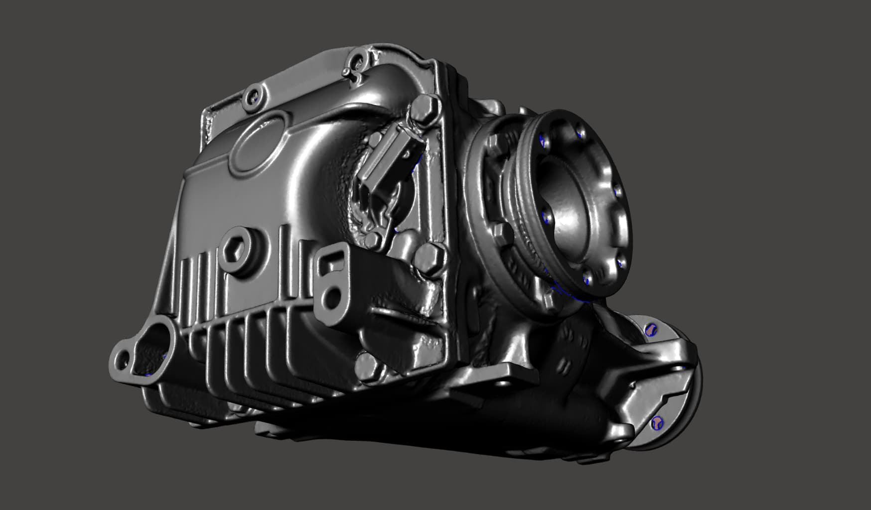
I’m currently working on 3D scanning most of the parts of a mazda rx8 rotary engineblock, for later publishement online as engineering resource.
Although the project needs higher precision and accuracy than the revopoint scanners can do, I thought it might be fun to try and we might learn a thing or two about the revopoint scanners capabilities and compare them to an industrial handheld 3D scanner, which costs a small fortune.
All of the data was collected in marker mode, from the same object, in the same environment, on the same table, same truntable, same markers and marker positions and same lighting situation.
The obejct was prepared by a light grey primer coat and scanned from both sides separately and aligned the two sides by a circular scan around the objects base which was deleted after the alignment and only used the two side scans for the final mesh. Alignment, merging, meshing and post processing was done in geomagic wrap. For the pop3 scans I had to place additional markers due to the smaller scan area compared to the other two scanners.
I kept the industrial scanner data as reference and compared the others to that. The reference data was aligned by its features to the global cordinate system and the pop3 and range scans were registered to the reference scan in multiple steps to ensure the lowest possible tolerance fitting.
The pop3 and range scans had to be scaled down just a little bit, to match the overall dimensions of the reference scan data. Scaling factors: pop3 - 0.995, range - 0.996
Hopefully the necessity for scaling will be negated once we have the opportunity to calibrate our scanners ourselves.
Polycount was left as high as I could get out of the raw data. All models have between 6.7 and 8million faces.
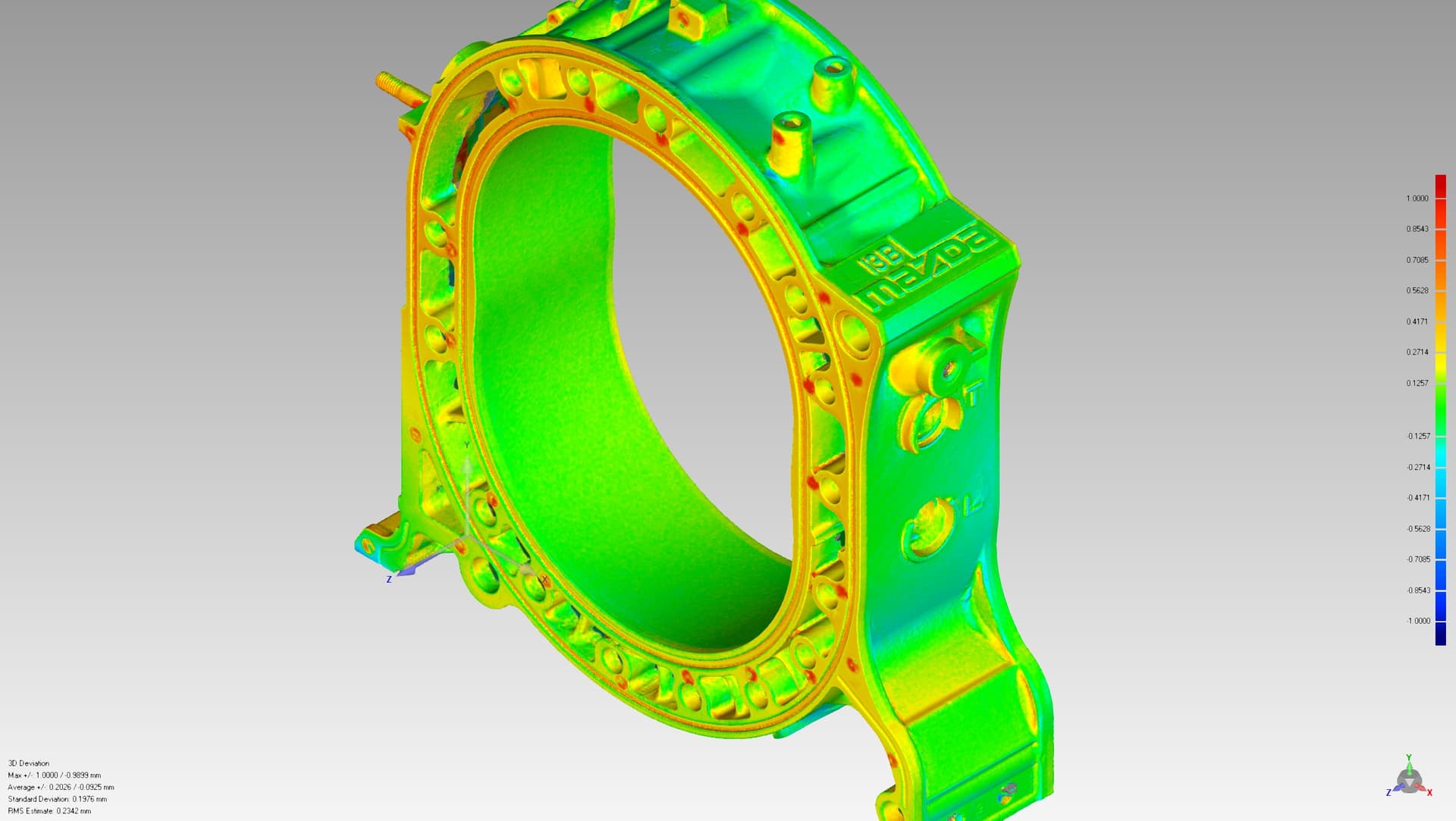
Here are the results:
From left to right: Range - POP3 - industrial scanner


From left to right: Range - POP3 - industrial scanner


From left to right: Range - POP3 - industrial scanner


Theres a major dimension I choose to show you. These rotor housings have a nominal width of 80mm. In reality the object was measured to be 80.09mm wide, including the grey primer coat.


General deviation maps:
range vs industrial scanner:

pop3 vs industrial scanner: (the red dots are markers)
range compared to pop3

These results again prove that these scanners are pretty useful tools, however for your own good, do not overestimate their performance. Be conservative when using them for precision work and always use regular measuring tools to verify dimensions!
7 Likes
A weekend project:
My gf wanted a rear wing for her beautiful RX8. I remembered we had a bootlid with an original mazda wing laying around in the loft, so I grabbed it to prepare it for respary. We decided to keep her original bootlid untouched and use the complete winged bootlid instead.

I noticed some rust sports that needs to be taken care of, but most inportantly, even though this wing is an oem option on the rx8, the mounting method is rather weak. Theres just 4 through bolts attach it to the outer skin of the bootlid, so the wing is mounted flimsy, it can flex the outer skin quite a bit, which is not good. The outer skin can weaken and crack around the bolt holes over time and can also grow rust!
I hatched a plan to stiffen up the mounting by connecting the original bolt holes to some more additional bolt positions on the inner skin.
First I had to scan the relevant inside area of the bootlid. The two bolt positions in the back are deep under the inner skin, the scanner could not possibly see it. They also did not quite line up with the access holes, so I had to enlarge them. I’ve put on an extended socket over the bolt head to be able to extract an end position and an axis from the scan later.


To scan the area, I used the POP3 scanner connected to my phone, along with a generous amount of 3mm markers.
The scanning spray this time was weld inspection developer spray, because I didn’t have to worry about the paintjob.

Scanning went pretty smoothly as every other time with the POP3. The software go more streamlined recently for what I’m really happy.

Created a mesh that best represents the original surface as-is, but I also made one that has all of its holes filled up and smoothed out, this one will be used later to cut solid models with in cad.
One of the greatest things in scan data is that I can use it to mate oddly shaped, even organic shaped parts to other oddly shaped parts wit perfection, by using the scanned data surface to split my solid models and create an inverted surface which will fit exactly to the original part.


Here is the resulting cad model of the bracket I came up with:


It basically acts as a bridge between the mounting points of the wing on the outer skin, to additional bolt holes on the inner skin.
The marked areas are direcly derived from the scan data.


Printed out of abs:

Theres one bolt hole boss on the model which is for the bolt that is deep under the inner skin, which I had to design with quite a large diameter in order for a 8mm socket to fit in. This requires for the access hole in the inner skin to be enlarged even further, so I figured I might as well print a cutting and drilling marking template to make my life easier. This time the surface was just thickened to 1mm and cut the necessary holes into the model as well.


And the end result: The wing now sits stiff as a board comapred to its original state.
Meanwhile the rusted areas were also treated so now the bootlid and wing is ready for the paint shop!


4 Likes
Loving the POP3! This was a 5 minute scan for a differential swap in a rally car. No careful preparation, no cleaning, just a bit of scanning spray, done in feature mode on android phone.
Raw pointcloud processed, cleaned and decimated in geomagic. Perfectly fine for designing diff mounts.

8 Likes
What a great showcase, I particularly like the comparison between scanners, abs the explanation of what software you’re using ![]()
Great results.
1 Like
Hi Lajos,
Glad to see your post again! Thank you for sharing such a great showcase. ![]()
1 Like
You mean Fused Pointcloud , Raw Pointcloud can’t be exported from RS5, raw pointcloud is an unorganized Pointcloud , Fused Pointcloud is organized and is not under RAW category .
Nice scan ! Thanks for sharing !
1 Like
Yes, you’re right, fused point cloud. I meant no alignment, no cleaning done on them.
By the way, I wanted to suggest a change in the revo scan software. It seems like as the scan gets larger, the maximum available resolution gets lower when meshing. This means I cannot get a mesh resolution as high as I want, even though the data is there to do it. For this reason I export the pointcloud and process it in geomagic, so that I can set my mesh vertex distance exactly as I want it to when doing meshing, therefore I can get the maximum detail out of the data available. Later I decimate the model to my liking, leaving a dense mesh on detailed areas and a more coarse on smooth / flat areas. What I’m suggesting is changing the mesh quality slider to a vertex/point distance slider, where setting the vertex distance from 0.02 to 1mm available at all times.
Asking this, because I can achieve noticably better detail reproduction when meshing the data in geomagic over the highest settings in revoscan.
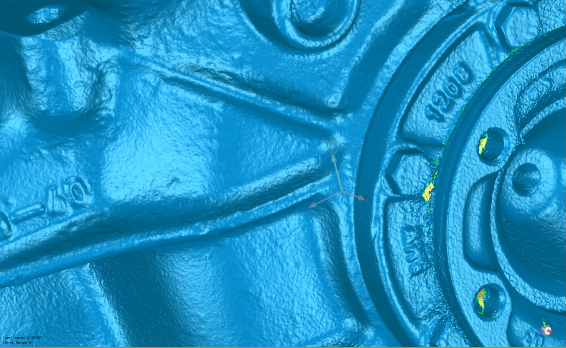
Not the best example, but maybe you can still see:

1 Like