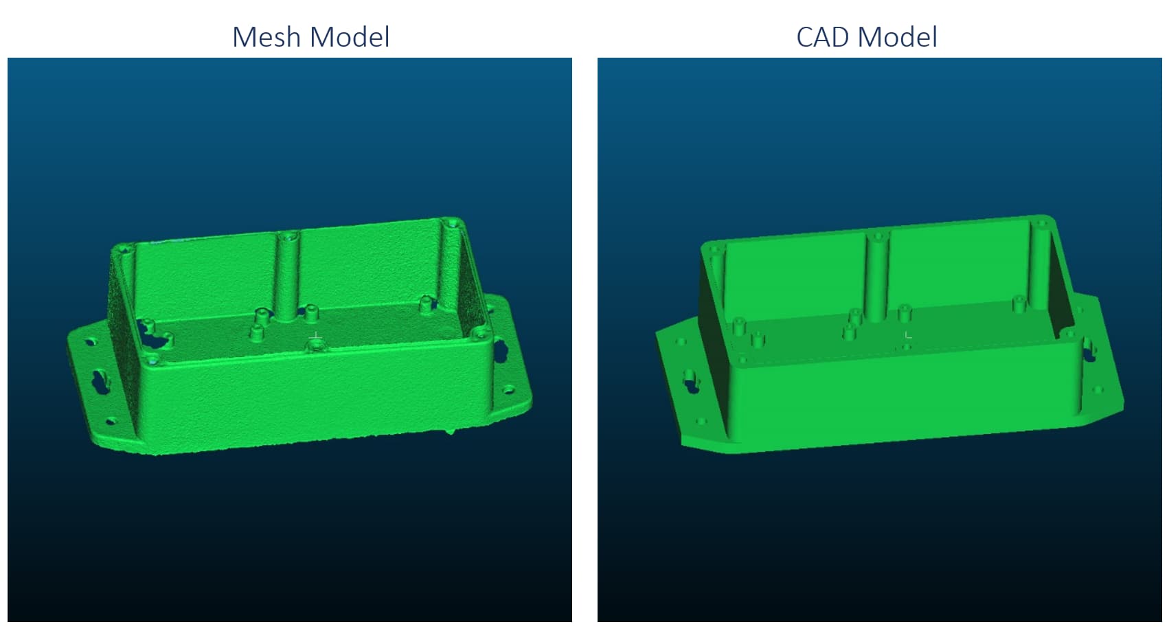
Often, laser scanning is done for reverse engineering or fabrication part verification. In this application, the laser scanner is used to either develop a CAD model for an existing mechanical part or to verify the dimensions of a fabricated part. The dimensional accuracy of the laser scan and noise quality is critical for accuracy and to disambiguate features. In this example, I have scanned a mechanical enclosure to compare it to an existing CAD model. The scan can be used to compare to a CAD model to verify the design, or in place of a CAD model when one does not exist to do design work.
I am using CloudCompare (www.cloudcompare.org)to do the analysis along with Autodesk Fusion 360 and AutoCAD (www.autodesk.com) for model conversion and inspection.

CAD Model
The CAD model was acquired from SparkFun Electronics (www.sparkfun.com). It is the Big Red Box Enclosure (https://www.sparkfun.com/products/11366) which comes with a prototyping board used for electronics projects. A 3D CAD model of the enclosure is freely available to download in Sketchup, STL, IDES, and Solidworks formats. I imported the Solidwoks model into Autodesk Fusion 360 and exported only the base to STL format to use for further analysis. There are some differences in the CAD model from the actual part. The rounded corners on the mounting flange are not shown as well as the lip around the top of the box. The CAD model provided by Sparkfun is probably not a fabrication model but instead a simplified design model.

Laser Scanning
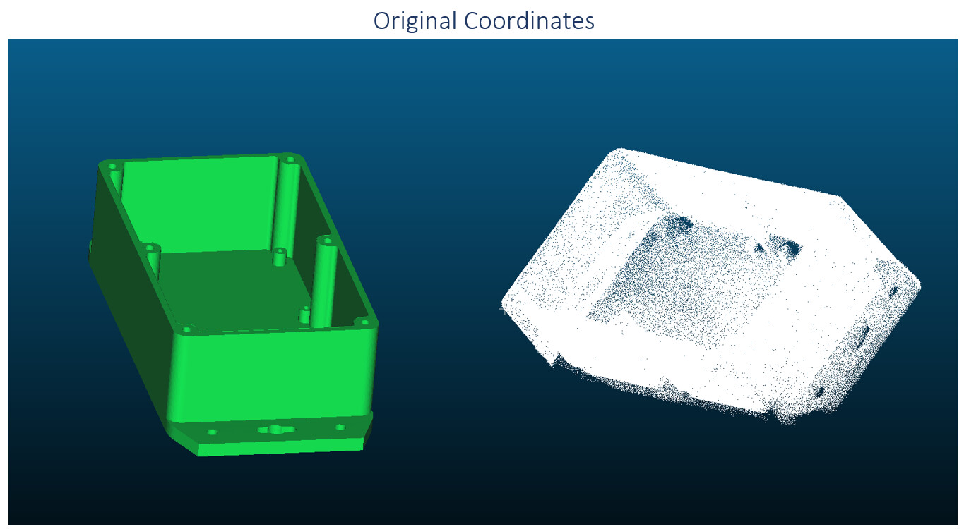
The laser scanning was done with the POP 2 in the High Accuracy Scan mode. The object was scanned on the turntable while the scanner was stationary to capture the exterior. Then, the scanner was held in hand to scan the interior. The surface was a bit reflective even though it got good results, but I applied a coat of Aesub Blue to dull the surface to compare the quality of the scans. The scan with the spray coating performed better in the final results. The scanning and processing only took a few minutes.

Scan to Model Registration
The coordinate system of the point cloud data originally did not match that of the CAD model, so a cloud-to-mesh registration had to be performed to align the models. This alignment was done in CloudCompare by first picking three common points between the two models to calculate a rough alignment that was then refined by an ICP algorithm. The resulting RMS of the final registration was 0.36mm and was calculated using 50,000 points.

Point Cloud Analysis
The laser-scanned point cloud was then compared to the CAD model in CloudCompare by analyzing the signed distances of the points to the mesh surface. The point cloud is then colored with a heatmap, and a histogram is provided to give the average metric of the fitting quality. The points are within ±1mm, with the average being 0.15mm. The mean offset from 0.0mm is likely due to the differences in the CAD model, causing a population of the points to be beyond 1mm from the CAD model surface.


Model Deviations
The sides of the enclosure are set out by 0.45mm – 0.54mm at the top of the flange, while the top of the enclosure is tight to the point cloud. This is on account of the plastic injection molded part having a draft angle to allow for mold removal that is not expressed in the CAD model. The laser scanner was able to capture the small lip around the top of the box, and it shows well in the point cloud and mesh models. The scan shows the base of the enclosure to be 0.26mm wider than the CAD model, but this could also be a result of the draft angle. The screw bosses at the bottom of the enclosure are shown to be in the wrong location in the CAD model.


Mesh Analysis
The deviations between the mesh model created from the point cloud and the CAD model are similar to those of the point cloud, and the mesh has enough detail to be used in place of the CAD model for design work.


Conclusion
The Revopoint POP 2 has sufficient accuracy and resolution to capture a mechanical part at a high level of detail and quality. The noise of the point cloud is with the tolerance needed to perform fabrication verification and reverse engineering of mechanical parts. In the absence of CAD models, the mesh model produced by the scanner can be used in mechanical design with a high level of reliability.
In case you need, here is a link for you to back the POP 2 on Kickstarter:
https://www.kickstarter.com/projects/2125914059/revopoint-pop2-high-precision-3d-scanner?ref=4grzc8


