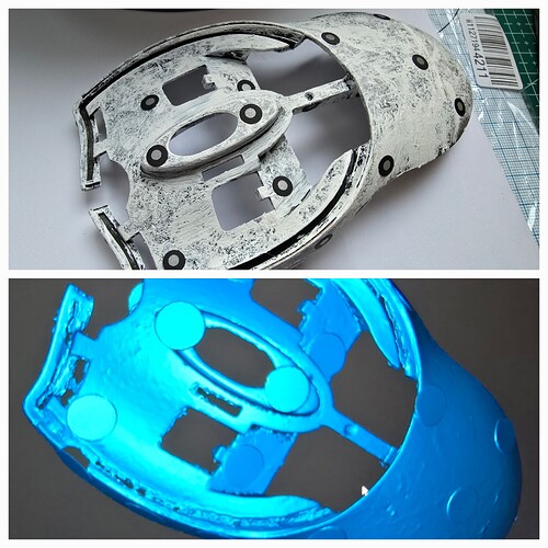
I prepped up a part last night, and scanned it today:

And, yes, those are dental picks applying the scanning dots.
Pre processing, during the scan:
I don’t have a camera to capture on the Android phone while the part is being scanned - tracking on ths size of dot is excellent in Marker mode with these little tracking dots.
And I’m reasonably happy with the data capture – enough is captured on the “down” side, that I should be able to merge the two scans I made together.
Here are the post-processed models of each scan:
The issue is plain, once looking at this: While scanning, the dark-ringed tracking marker dots occluded from the scan after post processing are HUGE in comparison to the dots applied.
This is the “down” scan in Meshlab
Is there an ideal sized marker that RevoScan expects?
I’m using a Mini: High detail, no colour, marker mode.
The version used is Android, v 5.2.2 (latest, at this writing - it tends to auto-update as new versions come out)
Input from Revopoint would be helpful here. This looks like the marker size was overlooked, or assumed to be excessively large.
Should I be requesting a feature where we could input the dimensions of the markers, so the software can scale how large a hole to “punch” out of the scan data?
I didn’t get this model into CAD yet to do a measurement, but the removed data around the marker looks like it has a diameter closer to 8 or 10 mm, instead of my wee tiny little 3mm markers.
From what I recall, while scanning, the red dots to indicate the markers were small and looked pretty much to scale as the actual size of them while in the midst of scanning.
I’m more than willing to pass on my project data to the R&D or dev team. Or, to answer any questions about this. Thank you for reading this far!


