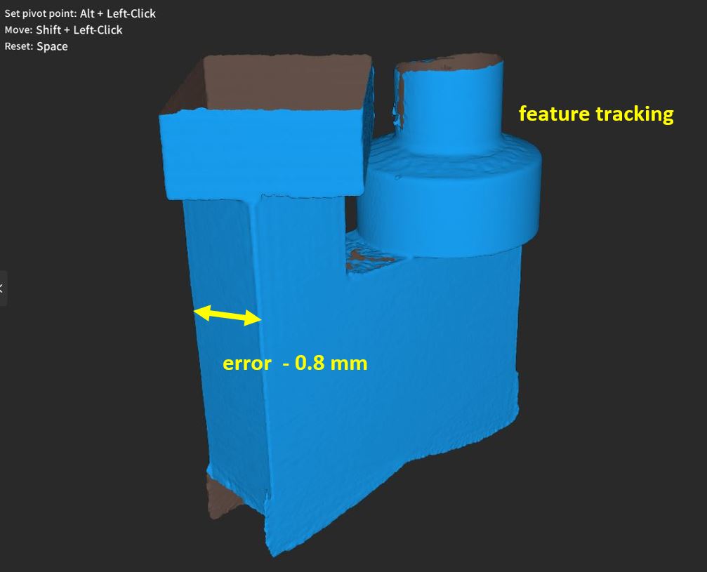
continue to play with my new POP3… I bought it mainly for reverse engineering purpose so accuracy is my prime concern. Today I tried to scan a piece of ABS block about the size of my palm, the thickness of the block is 25.7 mm which I want to compare with that captured by the model. If the block is scanned on the turn table using feature tracking mode, tracking loss occurred every time so accuracy is irrelevant. Then I tried to add more features including a piece of wood block, a PVC pipe joint and a sock, tracking lost was not reported but the accuracy is rather poor. Finally I tried marker tracking without any added feature and the accuracy is markedly improved although it is not close to the advertised value of 0.0x mm. This is consistent with my earlier finding that using marking tracking results in a better scanned model appearence of the small bust that came with the scanner ( Marker tracking always better? - #2 by PUTV )


.1 mm is about right for the POP3 (single frame accuracy). The .05mm specification (single frame precision) is that the frames will be within .05mm of each other. I suppose you could get detail between .05 and .1mm during the fusion process from extrapolating between multiple frames but I think that’s as likely to be noise as detail. I reserve the right to be totally wrong.
I can’t explain the poor feature tracking results. Is this standard or advanced fusion? All fused at the same point distance? Overscanning? I tend to scan overly large things requiring a lot of merging where the errors can really pile up so I’m curious what the answers to this might be.
Advanced fusion was used in all cases using default parameter settings. Not sure what over scanning referes to but all were done on the stock turn table and scanned over one complete turn only. All are one-time scans, no merging was done.
If you have the willpower and time, I’d try fusing the feature tracking scans at the same point distance that it suggests for the marker tracking version and see if it is any different. Revoscan probably suggests higher point distances for the feature tracked scans due to the extra volume of the additional objects. You can also try eliminating the extra objects in keyframe edit mode (warning: destructive edits!). After doing so you might see that a different point distance is suggested, although you usually have to reload the project to force it to re-evaluate.
I’ve also seen advanced fusion sort of gloss over some bad frames, even though the result looks good there might be a concealed error contributing to the final result.
Hi @new23d please re calibrate your scanner if there is greater error than it should .
The accuracy of a 0.05mm is a single frame accuracy done on a lab instruments , you would be never able to measure it at home the way you do . It is an accuracy of a point … point cloud accuracy , not a mesh .
You should have around 0.02 error not 0.8mm
Please recalibrate your scanner , it will help in the tracking , and both IMU and Board Calibration
Please scan the object with exactly the same distance from the camera , one cm forward it back will affect the accuracy dramatically , it is s 3D structured light scanner , the highest accuracy is at the closest distance only .
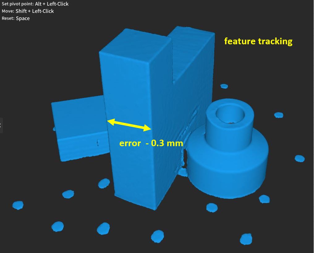
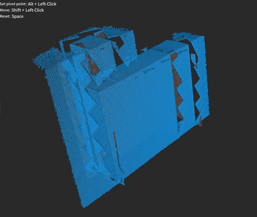
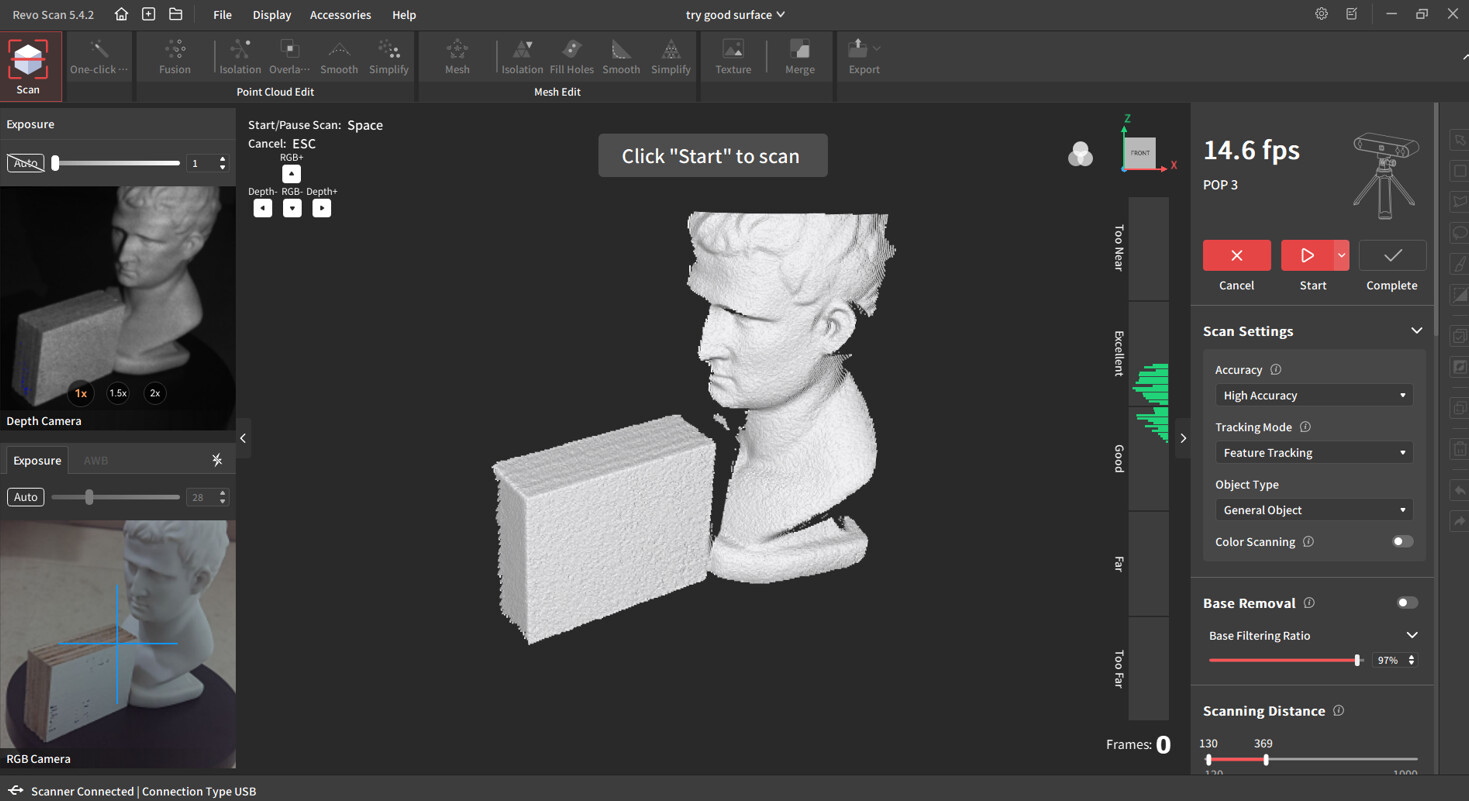
Just calibrated the scanner again and retry scanning with the same set up. Object on the turn table and scanner on the tripod. With the plastic block scanned alone, tracking is lost as experienced before. This is the process :

The fused model is a mess :
With two features added to the top of the block, the result is much better. The mesh model looks nice but the dimensional error remains bigger than desired. All the fusion / mesh parameter values are suggested by the software. As shown by the video, the distance is in the good/excellent range. 24 cm to be precise.

One more suggestion in addition to what I mentioned before: I’d speed that turntable up. You’re capturing at least 4x the number of frames you need.
Hi @new23d the distance need to be too near/excellent for the best accuracy .
Don’t use one click option if you looking for accuracy . The block by itself is not a proper object to be scanned using 3D structured light scanner , you can model it in 10 min , beside it do not have any features that the scanner need to keep tracking .
The speed need to be maximum 30 sec per one 360 rotation .
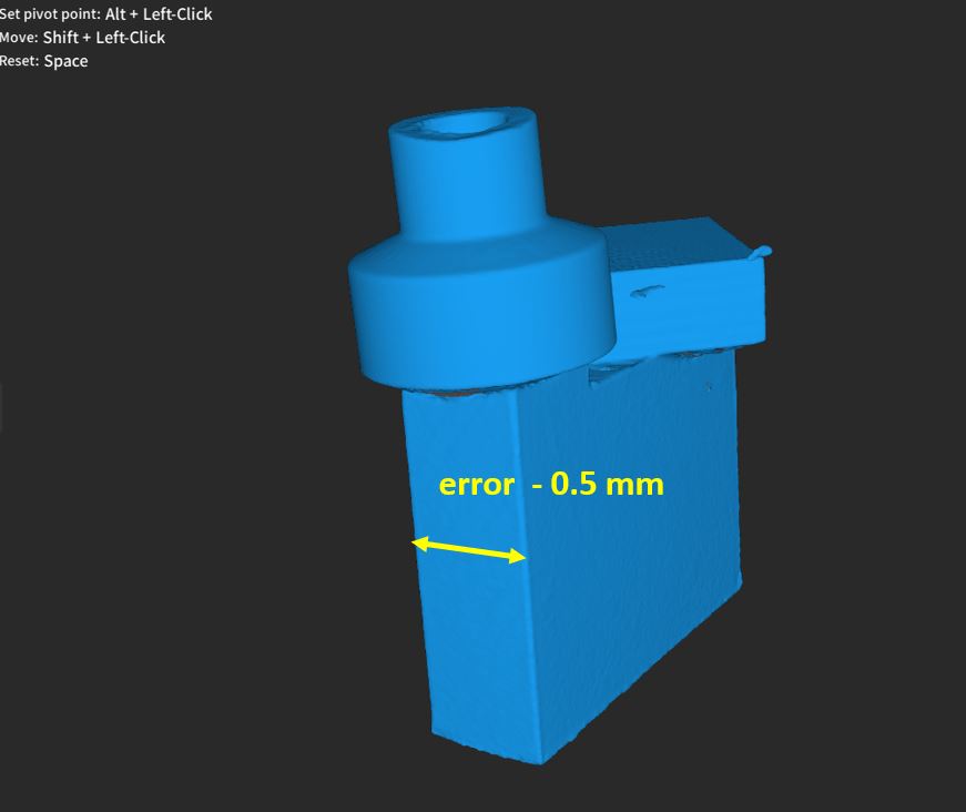
All 3D scanners I tested from Revopoint are always slightly above its specs so as much as 0.5mm error is little too much here .
Can you send your block scan project to me at putvmail@gmail.com for investigation ( full project )
Thanks for the advice. Project files just sent to your email. I did not use the “one click” options but the fusion and mesh buttons seperately.
Nothing here yet …
What was the original measurements of the block ?
The block is 25.74 mm thick
Hi @new23d
I checked the files and the errors was exactly the same .
I don’t like the surface , there are too many artifacts that could affect the accuracy , please try to scan anything else that is not from resin, reflective or translucent material with IOR . To reduce the amouth of noise , keep the distance between too near-excellent , good distance will lose accuracy , use 3D spray to matte the object down .
Try to change the position of the scanner , I can see it affecting the surface as well with this type of a object .
You will never get accuracy of a 0.05mm , since that is a single frame accuracy and object is not spherical .
1 mm error is acceptable , but you should get better than that .
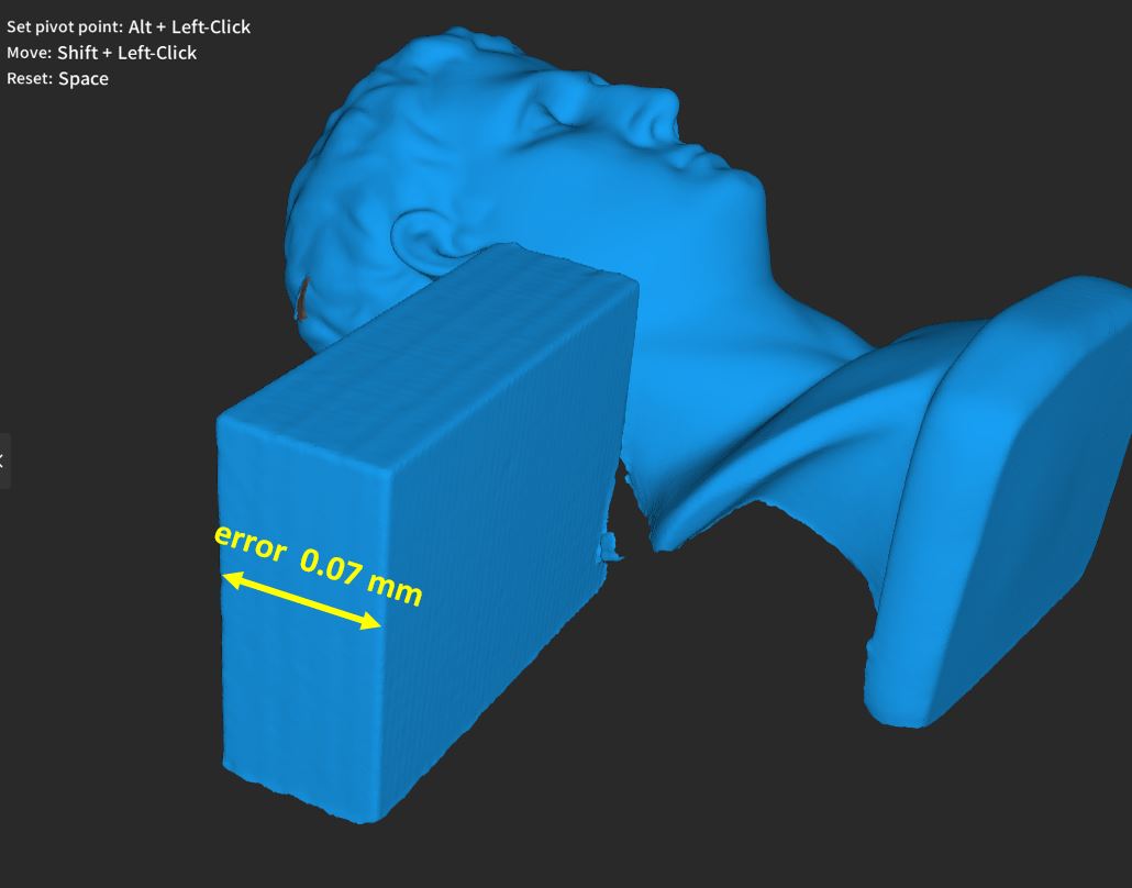
OK, just tried again using a piece of wood with matt-white surface as the object for checking the accuracy. The stock bust was put next to it to help tracking. The error is 0.06 ~ 0.07 mm , hope this is consistent.


That are already very good results , please stay in the near-excellent distance , going to excellent-good you will lose some accuracy . Use Advanced mode ( no quick edit ) , and make sure you calibrated the scanner well with the board because I am observing some noises on the preview shots that are rather too prominent , it should be more smooth .
But you make already good progress , make sure the distance from the center of the turntable to your scanner is around 13-15 cm
Tried the baby powder + alcohol coating trick and did the scanning again. The error is now much smaller. Three scans done. Results are as follows.

the error I less than a human hair … so very much perfect
if you use a 3 microns 3D spray you will have even less , but don’t expect it to be 0.00 as that usually never happens, and not when scanning primitives .
but good job @new23d , practice makes perfect !

it is very rough , if you used MINI, you would see every strip in the scans ,
try a spraying bottle , or get zinc oxide instead , non nano version , cheap and last for a long time, you don’t have to make the objects white , just dust it slightly with the spray
I always buy this one : https://a.co/d/2pEulAy
As I will be using it on machine parts so abrasion by residue powder is a concern, is zinc oxide more abrasive compared with baby powder ?
Everything in this case is abrasive to some degree including baby powder . Purchase vanishing 3D spray to use with parts that can’t be washed off .
www.attblime.com ABX Super White or ABX Zero