INSPIRE 3D SCANNER IS LIVE ON KICKSTARTER
Learn more about INSPIRE:
Inspire is an excellent tool for getting CAD dimentions accurate for reverse engineering purposes. In this guide I will take you through the various steps from scanning to getting an editable model in Fusion 360.
The object I want to create in CAD is in several parts so it’s best to disassemble it and scan the parts individually.

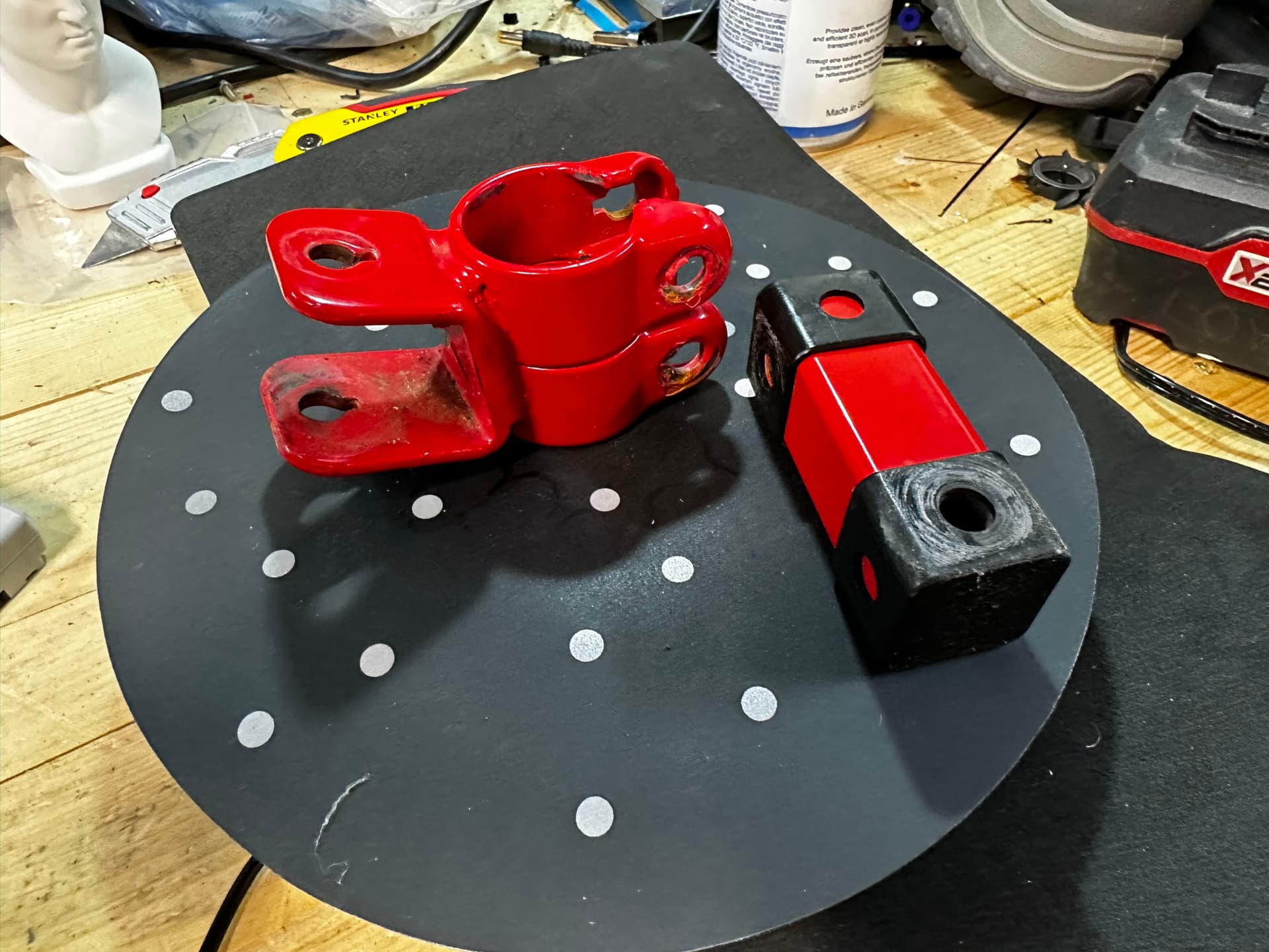
This parts are quite shiny so to give Inpire the very best change of getting a good scan, I apply some scanning spray. This isn’t strictly necessary.

Next, set up your scan. Think about what orientation your object needs to be in to get the best scan of all sides. For this item, vertical seemed like the best way. Also, it’s important to have the David bust watching you as you scan.

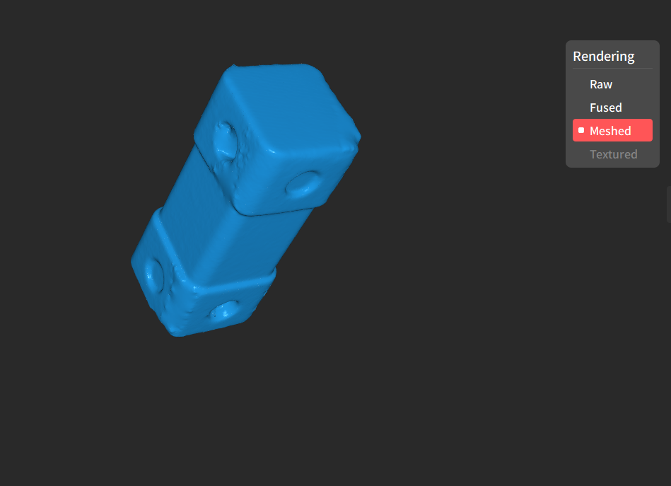
In Revoscan 5, I decided to scan this in marker mode as the item is very uniform in shape.

Once you have the object scanned, first fuse it, then tidy up the point cloud using the Isolation, Overlap, Simplify, and Smooth tools. They are pretty self explanatory but some experimentation is advised to get the best scan.

Once we’re happy with the point cloud, we can mesh it and export it as a stl
Next, on to the more complex part. Again, I used marker mode for this.


Due to the shape, I had to scan this at multiple angles. The way I do this is to take 4 seperate scans and then merge them in Revoscan. You could pause the scan and re-position but you would need to scan in feature mode for this to work. I find seperate scans and merge to be more relable.


Once we have our scans, we can clean them up as before using the tools and then hit the Merge button.
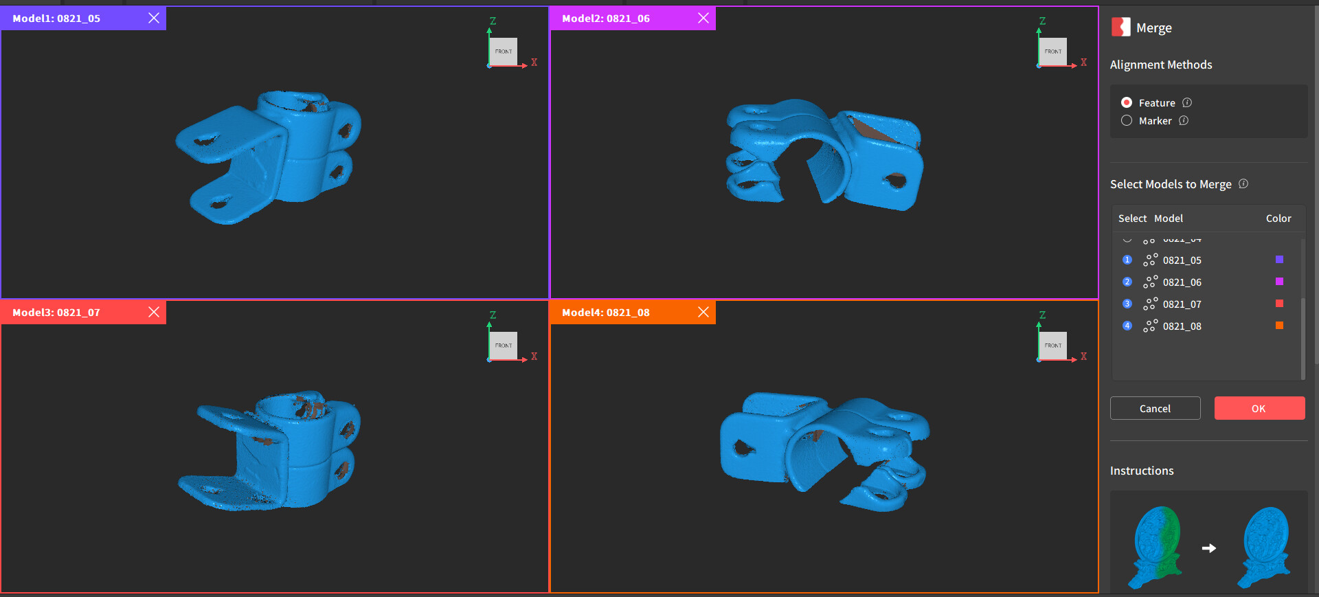
This automatically merged in feature mode without issue. You can use marker mode to select various point pairs to use if automatic alignment fails.
And we have our finished scan of the second part

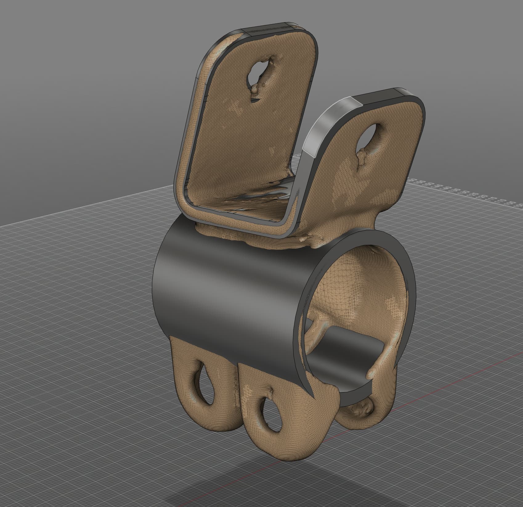
Now, on to Fusion 360. Inset a mesh in to the workspace. I have started with the simple part first.

Next, we need to align the scan with our workspace coordinates. I prefer to do this manually but changing the view between top, side, front, etc. and nudging the model until it’s lined up.

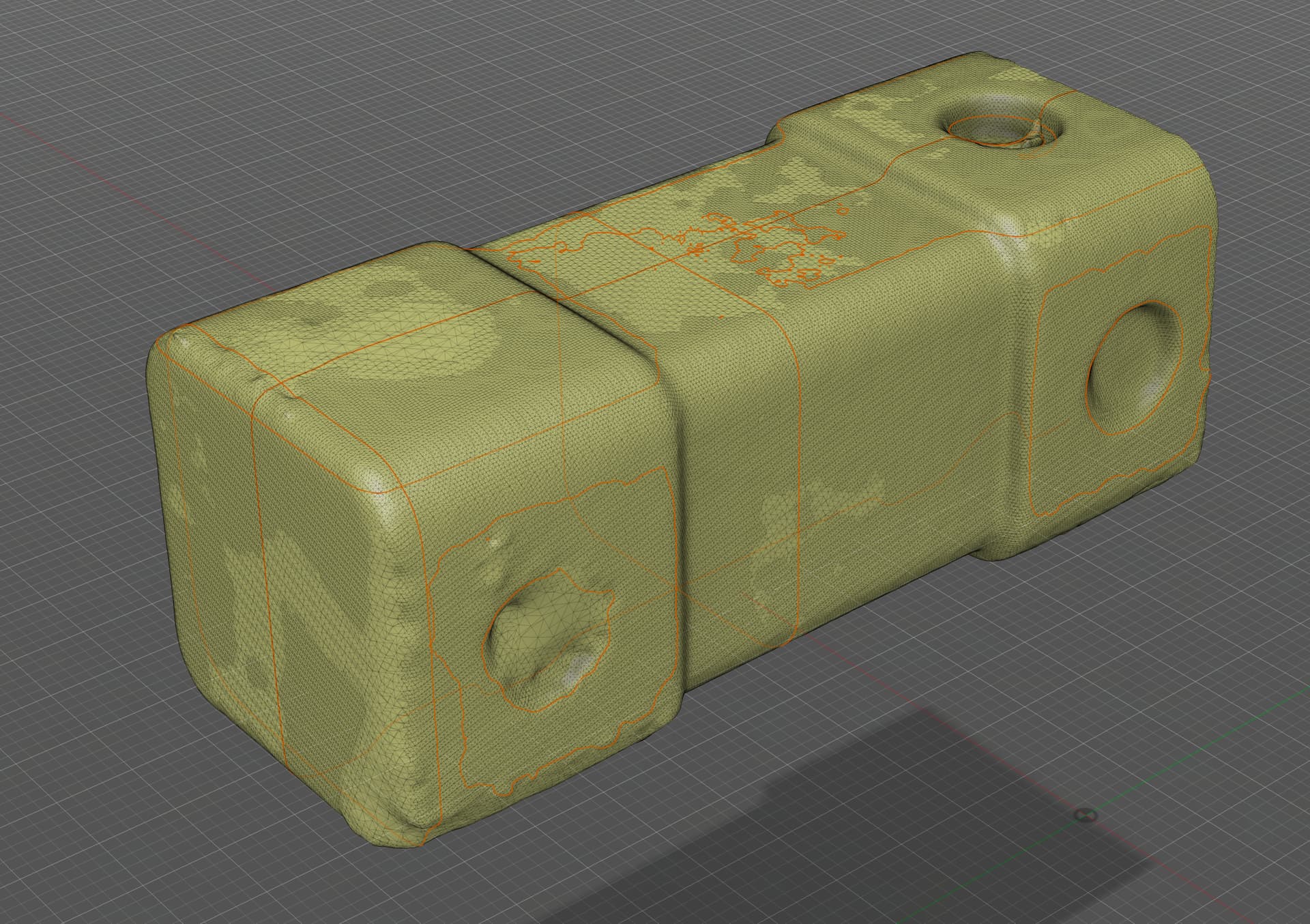
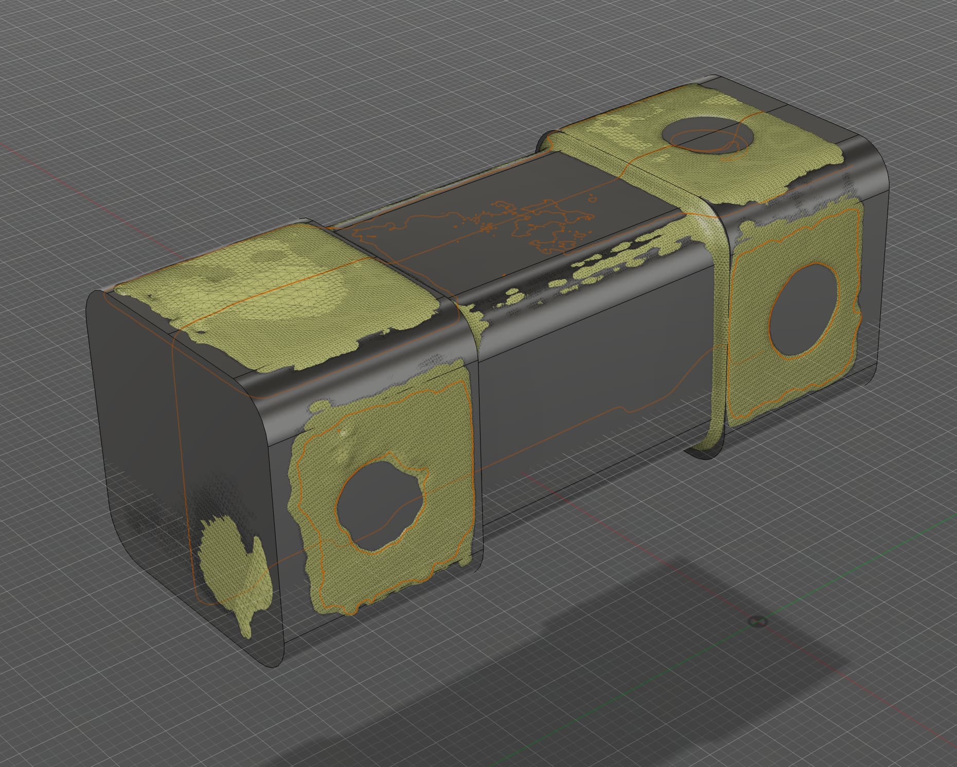
In the mesh workspace, we need to click the Create Mesh Section Sketch button. It may be under the dropdown on your screen though.
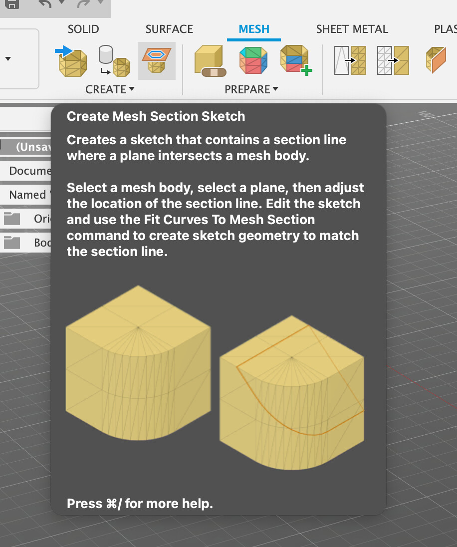
Using this, we can create outlines of sections of the model to use as references for our sketches later on.
It’s a good idea to take several of them to cover all the major features.
Once we have our section sketch, right mouse on the sketch in the tree view and select Edit Sketch

Then go up to the Create Menu and select Fit Curves to Section Sketch

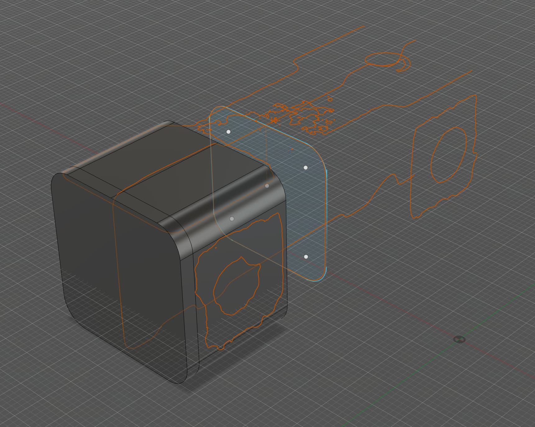
From here, you can fit various shapes such as circles, lines, curves, etc. to the sketch to make a fully enclosed sketch.

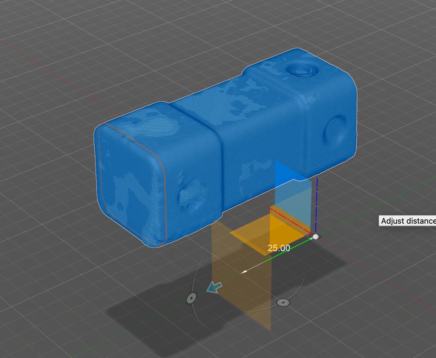
Once we have the first bit drawn, we can come out and go in to the Solid workspace, and extrude the shape we just drew
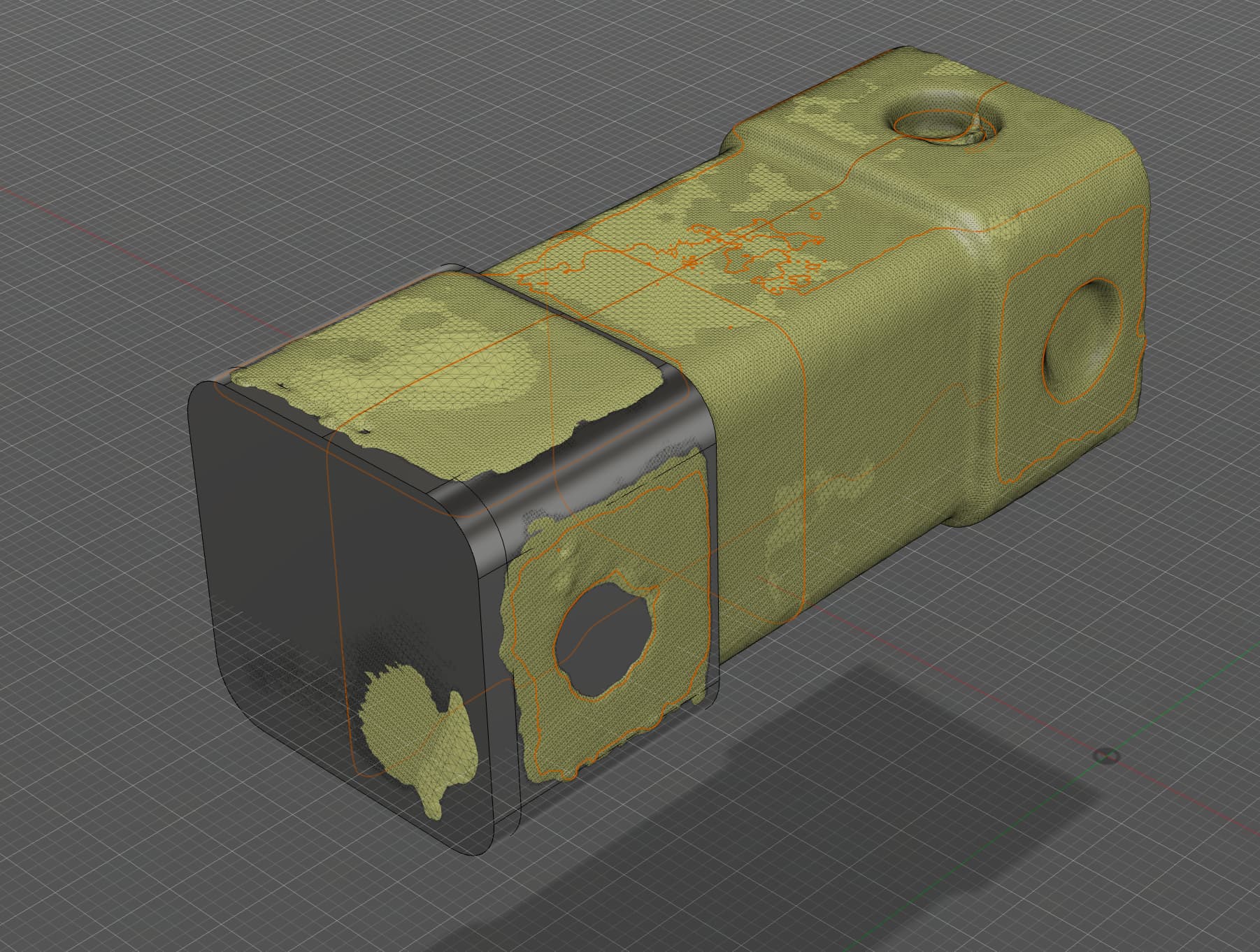
Moving on, we repeat the process as many times as necessary to build up the sections of the model
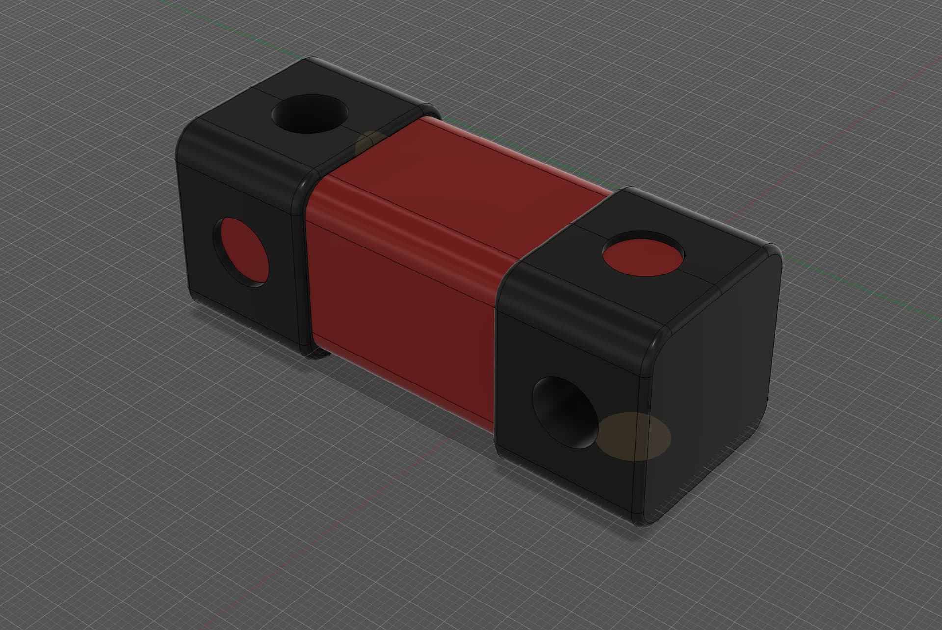
Add a bit of colour, and there we go
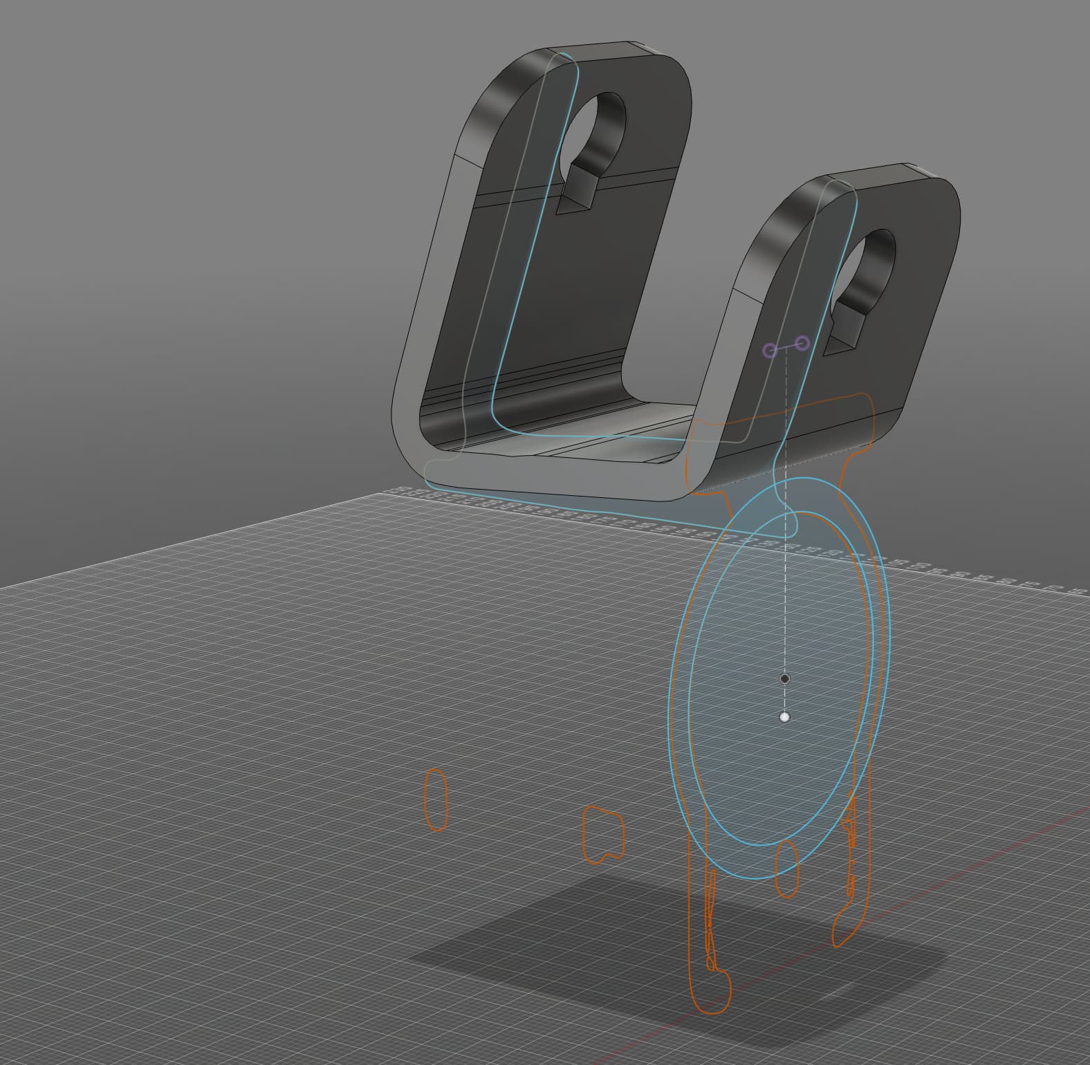
Now we follow the exact same process for the second part. This one is more complex and so is trickier to do.
First orient the part

Create section sketches

Extrude

And repeat

Draw some bolts of the correct dimentions and assemble:

And here’s the final assembly, rendered.
