
To start, download our scanning software, Revo Scan from https://www.revopoint3d.com/.


- Home Page
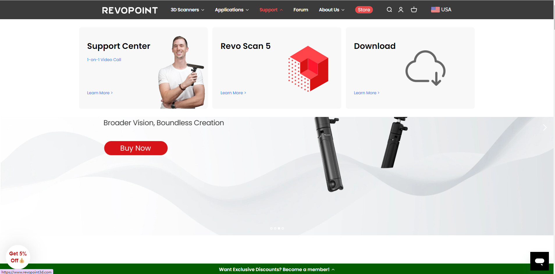
Open Revo Scan, and you can see the connection status of the scanner, the New Project button, and the project history on the Home page.

Click the icons on the right of projects to switch the display mode of your projects.


On the Learning page, you can find instructions and tips about how to use Revo Scan.


You can also recalibrate the scanner at the bottom of the Navigation Pane and click the settings icon in the upper ringht corner for language selection.


- User Interface
Click New Project to enter the project interface.

At the top, you can see Menu Bar, Title Bar, and Tab Bar.

You can see the software version on the top left of the Menu Bar. If you want to return to the Home page, start a new project, open your project, or connect accessories, you can click the icons on the Menu Bar.
![]() : return to the Home Page
: return to the Home Page
![]() : start a new project
: start a new project
![]() : open your project
: open your project
Please click Help to get the User Guide and online support, or give us feedback if you encounter any problems during use.


The Title Bar shows the name of the project and you can rename the project by clicking it.

The functions on the Tab Bar will help you process the models when you finish the scan.

On the left is the Project area, where you can see all the models of this project and their properties.

The area in the middle is the 3D Display Window, which displays the scanned surface of the object during preview or the scan data that is being captured or has already been captured.


It also shows the results when you process the models.

The Scanner Info area shows the scanner connection status.
Click Connection Tutorial for a detailed guide on connecting your 3D scanner to a PC.


Use the three buttons on the Operating Menu to start a new scan, cancel, start, pause, and continue your scan, or complete the scan.

Click the Switching Scan Mode button to choose continous mode or Single Shot mode.

In the Scan Setting area, you can select your scan’s accuracy, Tracking Mode, and Object Type as well as enable or disable Color Scanning before staring a scan.

- Pre-Scan Settings
The preview of the model will show in the 3D Display Window in the middle of the page after you connect the scanner.

After connecting a scanner, the scanner’s name and frame capture per second are displayed in the Scanner Info area.

You can select High Accuracy, Standard Accuracy or High-speed(18fps) modes base on your needs.

In High Accuracy mode (Not available for INSPIRE), the post processing time will be longer but the result are more suitable for applicationss needing more detail.
In Standard Accuracy mode, the model processing speed is faster and is suitable for general scanning applications.
In High Accuracy(18fps) mode, the model processing speed remains the same as the Standard Accuracy mode but the frame rate reaches 18fps and it is suitable for large objects and people scanning applications.
Next, you need to select Feature Tracking or Marker Tracking.

Choose Feature Tracking mode for feature-rich objects like faces or sculptures.
And for items with simple geometric features like a football or a cup, stick markers on the object and select Marker Tracking mode.


Now, set the Object Type by selecting General Object, Dark Object, or Face.

General Object mode is best suited to scan objects with unique shapes.
Dark object mode is designed to scan objects with darker surfaces and Face mode is designed to scan people’s faces.
Enable color scanning if you want a color model.

If flat surfaces around the object are being captured during your scan, enable Base Removal to prevent them from being scanned.


When scanning a object with many flat surfaces, turn off this function to avoid to deleting any of the object’s surfaces.
Adjusting the Scanning Distance settings helps the scanner see the object within the selected distance and prevents the scanner from capturing anything outside that distance.

To connect other accessories, like the dual-axis turntable or handheld stabilizer, you can connect them via Bluetooth either in the Accessories menu or below the Scan Setting area.


Before staring a scan, adjust the scanner’s distance from the object until the distance indicator bar displays green.

In the Depth Camera’s preview window, you can either turn on Auto Exposure or manually adjust the exposure.

When adjusting the exposure, red indicate that the object is overexposed while blue shows that is underexposed.


Adjust the explosure till the object has a few red or blue areas or blue areas as possible.

If capturing a color scan, also adjust the RGB Camera’s exposure. Either set it to Auto Exposure or adjust it until the preview window’s colors look clear and sharp.
If your 3D scanner has flash LEDs, you can turn them on or off with the lighting icon in the RGB Camera Preview window. You can also adjust the White Balance of the RGB Camera here.


- Scan
When you’ve finished selecting all your scan’s settings, click the Start button to begin the scan.

When Color Scanning is disabled as you scan, you’ll see green areas showing what is currently being scanned and blue areas representing already captured areas.

If Color Scanning is enabled, the colored areas represent the already captured areas.

To deal with loss of tracking during a scan, move the scanner to a previously scanned area and wait several seconds for the scanner to regain tracking. Then, hold the scanner steady and continue the scan.

You can click the Pause button to stop your scan at any time. If the model is not complete yet, you can continue your scan by clicking the Start button. Once the object is scanned, click Complete to finish your scan.

If you want to redo the entire scan, choose Cancel to restart your scan.

- Post-processing Edit
When you finish your scan, you can use the functions on the Tab Bar to process the model.


You can use One-click Edit to automatically process the model.

Or you can manually adjust and complete Fusion, Mesh, Texture(only for colored models), and other optionnal processes.


(1)Fusion
Fusion merges captured point cloud data into a unified and accurate point cloud model.
Setting a smaller point distance result in a more detailed model.

The Isolation identifies and removes isolated points in point cloud data.

Use Overlap Detection to identify and delete overlapping data in the point cloud.

Smooth can make the point cloud smoother.

Run Simplify to reduce the number of points in a point cloud.

(2)Mesh
When you‘ve finished editing the point cloud, use Mesh to convert point cloud data into a solid 3D model. Setting a higher quality parameter will result in a denser and more detailed mesh model.

The Isolation function here detects and removes isolated mesh parts.

The Fill Holes tools repairs or fills missing areas or holes on the model. You can use Rectangular Selections, polygon Selection or Lasso selection tools to help you select multiple holes at a time.

The Smooth function intelligently smoothes and reduces noise in a mesh.

Next, Simplify the mesh makes the data more manageable for storage, processing, and sharing.

(3)Texture
Finally, choosing Texture to make the model’s colors more realistic.


There are Instructions below each of these tools that explain how they work.

Also, you can use the tools in the Tool Bar to edit the model.

If you nned to scan several objects or areas for one object, click New Scan on the Tab Bar after you finish one scan to start the next scan. When you get all the models you want, you can choose Batch Processing and select them in the Project list to edit them simultaneously.

You can even edit the original point cloud data by choosing Key Frames Edit.

(4)Merge
To merge several models, click Merge on the Tab Bar and choose the models you want to merge together. You’ll see that every model is shown in a different colors.

With Feature Alignment, you can select up to 9 models at the same time. The overlapping area between any two models should be at least 10%.

When choosing Marker Alignment, only 2 models can be merged at a time. You nust manually select at least 3 corresponding marker points on these two models. It is recommended to spread out marker when placing them.
The specific steps for Marker Merging are as follows:

- Export
Once you have finished editing the model, click Export and select a file format to export your model.
Select STL if you want to 3D print your model.
Select OBJ if you are going to use it for 3D design.
Select PLY for the standard 3D format.

One last thing, we are constantly updating Revo Scan, so don’t forget to update your version.
If you want to learn more, please follow our community!